head and boot
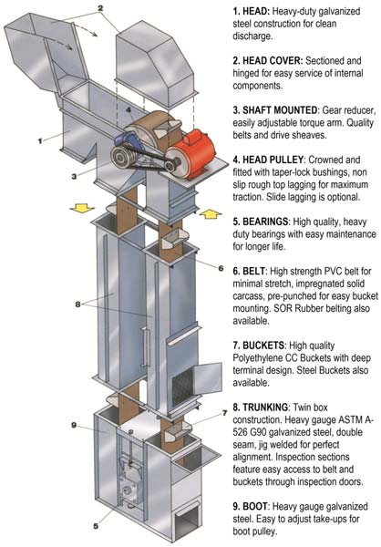
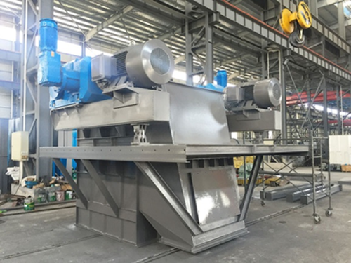
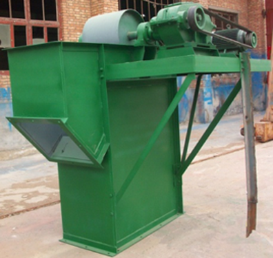
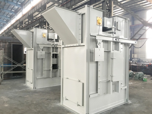
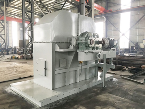
Bucket Elevator Head and Boot
The whole bucket elevator includes five parts: the head, the driving device, the middle box, the boot, and the lifting parts. The five major parts are designed and produced according to a certain precision. Finally, it is perfectly assembled to meet the requirements of use. Its functions are:
The shell of bucket elevator head should ensure geometric accuracy and sufficient rigidity, the head shaft and head wheel should ensure sufficient strength and running accuracy, and the selected head bearing and its seat should have a certain safety factor.
The structure and arrangement of the drive device must meet the power and transmission needs of the bucket elevator, the layout of its location must take into account the stability of the equipment, and its transmission mode should be as compact, concise, and easy to maintain and repair as possible. Reduce the weight of the drive unit as much as possible.
Although the intermediate box looks simple in structure, its precision and rigidity requirements cannot be ignored. Since a bucket elevator with a length of tens of meters or even hundreds of meters needs to ensure the running accuracy, the intermediate box plays a huge role. First of all, it must support most of the weight of the entire bucket elevator, and its compressive strength and operating vibration should meet the requirements; secondly, in order to ensure the installation accuracy and interchangeability of a dozen or even dozens of intermediate boxes, it must be Design and manufacture follow the principle of mass production, and there must be a certain tooling and mold to ensure its straightness, flange flatness, rigidity and its diagonal accuracy.
The bucket elevator boot is at the bottom of the whole equipment. Its function is to support the whole equipment and make it stable and reliable; the second is to ensure that the tension of the chain (tape) is constant and can be adjusted freely; The door is installed to facilitate the installation and maintenance of the chain (tape) and the hopper; the fourth is to set up safety protection devices such as material level gauge and speed detector at the tail as required.
The lifting parts include chains (tapes), hoppers and connecting pieces, which are also the key parts of the entire equipment. The design structure, manufacturing accuracy, heat treatment performance and safety factor of the chain (tape) directly affect the service life of the bucket elevator, while the structure, shape and accuracy of the hopper directly affect the lifting effect of the material. The above five parts are organically combined to form a complete bucket elevator.
TH type bucket elevator head and boot
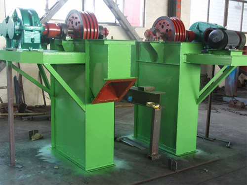
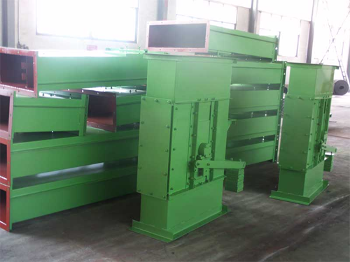
NE&NSE&TD type bucket elevator head
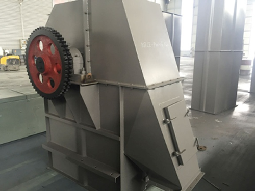
TGD type bucket elevator head and boot
The installation method of bucket elevator
1. The bucket elevator is firmly installed on the concrete foundation. The surface of the concrete foundation should be flat and horizontal, and the bucket elevator should meet the vertical requirements after installation.
The bucket elevator with a higher height should be connected with its adjacent buildings (such as silos, workshops, etc.) at the appropriate positions of its middle casing and upper casing to increase its stability. When installing, first install the lower parts, fix the anchor bolts, then install the middle case, and then install the upper case. The casing is installed successfully, and the verticality is corrected. Measure with a plumb line up and down the full height, and the error should be less than 10mm. The upper and lower axes should be parallel, and their axis lines should be in the same plane.
When installing a bucket elevator with a lower height, the upper, middle and lower casings can be connected and aligned on the ground plane, and then the whole is hoisted and fixed on the concrete foundation.
2. After the casing is installed, install the chain and hopper. The U-shaped screw used for the connection of the hopper is not only a chain joint, but also a fixing part of the hopper. The nut of the U-shaped screw should be tightened and secured against loosening.
3. After the chain and hopper are installed, properly tension it.
4. Add an appropriate amount of oil and butter to the reducer and bearing seat respectively. The reducer is lubricated with industrial gear oil. Calcium-based or sodium-based butter can be used in the bearing housing.
5. Trial operation. After the installation is completed, the empty vehicle trial operation should be carried out. Attention should be paid to the idling operation: it cannot be reversed or bumped. The idle operation should not be less than 2 hours, there should be no overheating, the temperature rise of the bearing should not exceed 250C, and the temperature rise of the reducer should not exceed 300C. After 2 hours of idling, the load test can be carried out normally. During the test run with load, the feeding should be uniform to prevent excessive feeding and block the lower part and cause "stuffy".


