
Cast steel
Original material option retained for engineering review against load, wear and service temperature.
Custom girth gear engineered from your drawing for dependable fit, documented quality and worldwide delivery.
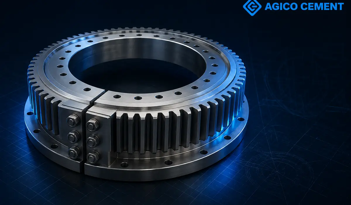
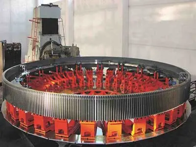
Girth gear being the most common part in the cement industry is used to drive large rotating equipment like rotary kiln or horizontal mills while its function is to transmit and change the direction of force through the large ring gear. Girth gear is generally composed of two to four segments that are assembled by counter screws together and tangentially fixed to the kiln body by spring plates. As per Chinese standards, high-quality ZG45, ZG42CrMO and other cast steel materials are used along with unique heat treatment to improves the hardness, wear resistance and impact resistance. Ausferritic spheroidal graphite cast iron is also used for the production of girth gears(which is a cast alloy, iron, carbon and silicon).
The clear majority of published knowledge about gear manufacturing relates to two main subjects: material quality and tooth accuracy. Girth gears are very large non-rigid structures that require special care during the machining of individual mating segments as well as the assembled gear blank itself. It is well known that a gear blank's mounting surfaces must possess certain measures of geometric accuracy, and that the gear's pitch cylinder must bear certain geometric relationships to those mounting surfaces. Moreover, the finest construction materials and the most precise tooth geometry have limited bearing on realized life when these geometric cardinal rules are not upheld. Indeed, the American girth gear rating standard — ANSI/AGMA 6014-B15 — disclaims validity when the required geometric relationships are not achieved. However, the R&D department of AGICO Cement has committed to meet the highest standard of girth gear manufacturing and has achieved its goal and striving for excellence.
Values shown below preserve the original product information while identifying what must be confirmed for the actual order.
| Product | Girth Gear / ball mill girth gear |
|---|---|
| Primary function | Transmit low-speed, high-torque drive to a rotating shell |
| Critical confirmation | Module, tooth count, pressure angle, pitch diameter and split joint |
| Manufacturing basis | Approved drawing, operating data and inspection plan |
| Supply scope | Custom manufacture, inspection, protection and export packing |
Original material option retained for engineering review against load, wear and service temperature.
Alternative construction or wear solution selected to match the actual duty and drawing.
Drawing-based girth gear supply for rotary kilns.
Drawing-based girth gear supply for ball mills and dryers.
Girth Gear drawing or complete dimensions
Equipment model and installation position
Module, tooth count, pressure angle, pitch diameter and split joint
Material grade, operating conditions and inspection standard
Material certificate and traceability review
Process inspection against the approved drawing
Critical dimensions and mating-interface verification
Product-specific NDT, hardness or balance checks when specified
Identification, surface protection and export packing
The Girth Gear transmits or supports operating load through rotating and stationary interfaces. Its performance cannot be judged by outside dimensions alone. Load path, mating parts, operating environment and the condition of the surrounding equipment all affect whether a replacement will fit correctly and run reliably. AGICO therefore reviews the component as part of the machine rather than treating it as an isolated catalogue item.
For a replacement project, the most useful starting point is the current drawing together with the equipment model and site observations. Wear photographs, failure location, maintenance history and measurements taken during shutdown help distinguish normal consumption from an interface, alignment or operating problem. This review allows the quotation to state the proposed supply boundary and the information that still requires confirmation.
Confirming the following groups of data reduces dimensional risk and avoids selecting the Girth Gear from a name or model reference alone.
Provide the available values, drawing references and photographs for applied radial, axial and transient loads. AGICO will compare them with the proposed Girth Gear configuration and identify any missing inputs before the manufacturing basis is released.
Where site data differs from an old drawing, mark the measured value and the measurement position. The final requirement should be agreed against the approved drawing rather than assumed from a nominal equipment designation.
Provide the available values, drawing references and photographs for mating diameters, fits, datums and bolt pattern. AGICO will compare them with the proposed Girth Gear configuration and identify any missing inputs before the manufacturing basis is released.
The production route for the Girth Gear is established after drawing review. It typically coordinates casting or forging route, heat treatment and rough machining. Process hold points depend on material, geometry and the buyer's inspection requirements. Critical datums and machining references are identified early so that later operations protect the interfaces used during installation.
Inspection is planned around product risk rather than added only at final dispatch. Material traceability and heat-treatment records; Critical journals, bores, faces and runout; Specified NDT at highly stressed transitions; Balance, contact pattern or assembly checks when applicable. When a test or report is required, it should be listed in the enquiry so that sampling, acceptance criteria and document format can be agreed before manufacture. Final release checks also confirm marking, quantity, surface protection and the packing list.
Maintenance teams should evaluate the Girth Gear together with its mating parts and operating records. Typical reasons for closer inspection include:
Unusual vibration, noise or temperature near the component. Record the location, extent and operating condition, then compare the finding with the equipment maker's limits and the site's maintenance procedure before deciding whether repair or replacement is appropriate.
Cracks, scoring, fretting or uneven contact marks. Record the location, extent and operating condition, then compare the finding with the equipment maker's limits and the site's maintenance procedure before deciding whether repair or replacement is appropriate.
Loss of alignment, excessive runout or repeated seal failure. Record the location, extent and operating condition, then compare the finding with the equipment maker's limits and the site's maintenance procedure before deciding whether repair or replacement is appropriate.
Dimension drift that prevents a controlled fit during shutdown. Record the location, extent and operating condition, then compare the finding with the equipment maker's limits and the site's maintenance procedure before deciding whether repair or replacement is appropriate.
AGICO can prepare a drawing-based Girth Gear for new supply or replacement service. The technical review covers the requested material, configuration, interfaces, inspection scope and documentation. If the original drawing is incomplete, provide measurements, nameplate information and clear photographs; the missing points will be listed for confirmation. No order-dependent dimension or performance value is treated as final until it appears in the approved technical documents.
Packing is planned for component weight, geometry, transport mode and destination. Finished surfaces can be protected against handling damage and corrosion, while loose accessories and documents are identified against the packing list. For international delivery, buyers should state the destination, preferred trade terms, lifting or site-access restrictions and required arrival schedule so that the quotation can separate manufacturing scope from freight and local handling.
Complete technical inputs reduce clarification cycles and help us quote the correct supply scope.
Send Your RequirementReview drawing and operating data
Confirm material, process and inspection plan
Manufacture and machine the component
Complete agreed inspection and records
Protect, pack and ship for installation
Yes. Send the drawing, equipment model and operating data for engineering review before quotation.
The agreed scope can include material certificates, dimensional reports and product-specific NDT, hardness or balance records.
Provide the girth gear drawing or dimensions, material, quantity, operating conditions, destination and required delivery date.
Yes. Packing and shipment can be planned for the component size, finished-surface protection and destination requirements.
Send your drawing, operating data and delivery destination for a technical review and quotation.
Request a Girth Gear QuoteRoom 908, unit 1, building 2, Huaqiang Xintiandi, Xiange Avenue, Anyang, Henan Province, China +86 18603725242