types components and fault analysis of rotary kiln drive
A kiln drive is a highly engineered thermal processing device capable of achieving various objectives, from catalyst production to metal recovery.
While most rotary kiln designs are tailored around the unique characteristics of the material to be processed and the processing goals, the bearings and drive components of a rotary kiln drive are fairly standardized. These bearings and drive components are included in the drive assembly and two trunnion bases.
Brief introduction of kiln drive
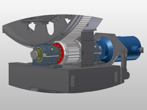
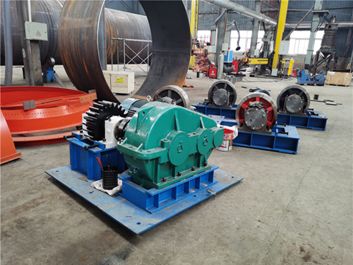
The rotary kiln drive primarily consists of a motor, reducer, pinion, and girth gear. These components together form the transmission part of the rotary kiln, ensuring smooth rotation and efficient operation of the kiln body. Specifically, the motor provides power, which is then reduced through the reducer to drive the pinion to engage with the girth gear, thereby achieving the rotation of the kiln body. Additionally, the rotary kiln drive includes an auxiliary drive, which is used to slowly rotate the kiln body during shutdowns for maintenance and cooling, ensuring the reliability and safety of the rotary kiln under various working conditions.
Available configurations include chain and sprocket drive, gear drive, friction drive, and direct drive. The choice between one drive type and another primarily depends on the required horsepower.
Kiln Drive Types and Components
1. Chain and Sprocket Drive
The chain and sprocket arrangement operates much like a bicycle; there is a large sprocket wrapped around the rotating drum, with a chain connecting it to a reducer and motor. The rotating motor turns the gearbox, which rotates a small sprocket connected by a chain to the large sprocket wrapped around the drum. The chain and sprocket rotary kiln drive is dedicated to smaller kilns operating up to 75 horsepower (55 kW). This arrangement is generally not suitable for large kilns above 75 horsepower but is very cost-effective and easy to operate for small-scale operations.
2. Gear Drive
Gear drive is best suited for heavy-duty applications running above 75 horsepower. Similar to the chain and sprocket drive, but instead of a sprocket wrapped around the drum’s perimeter, this drive has an actual gear around the drum. This gear meshes with a small pinion drive that rotates it. This type of drive is more expensive but performs better in heavy-load applications and requires less maintenance.
3. Friction Drive
The friction rotary kiln drive assembly is dedicated to smaller applications requiring low horsepower. This is common in drums of 6' (1.8m) and smaller. In friction drive, two of the four trunnion wheels are connected by a shaft and driven by a reducer and motor assembly mounted on the shaft.
4. Direct Drive
The direct rotary kiln drive assembly is used for medium to small drums with motors up to 75 horsepower. In this design, a shaft is mounted on the solid discharge end plate at the kiln’s outlet. The motor and reducer are directly connected to this shaft via a coupling or shaft-mounted device.
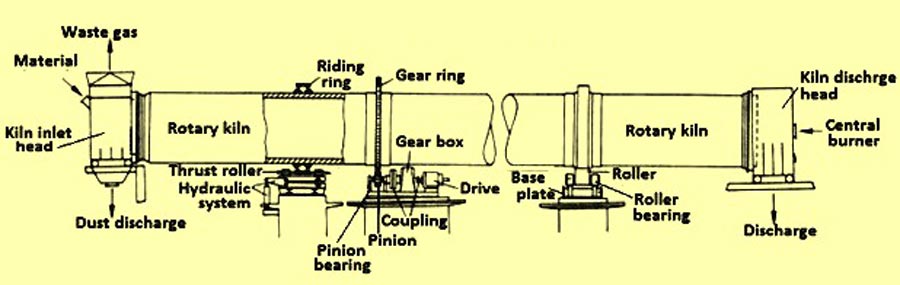
5. Trunnion Base
The trunnion base supports the weight of the rotating drum and consists of several key components.
6. Riding Ring
The riding ring is technically not part of the trunnion base but does contact the trunnion base at the trunnion wheels. Riding rings provide a surface for the kiln load to be distributed. They also provide strength for the ovality and integrity of the shell.
7. Thrust Roller
Thrust rollers prevent the drum from drifting or moving horizontally by pushing against the riding ring.
8. Trunnion Roller
Trunnion wheels act as the support for the rotating drum shell. They ensure smooth and concentric rotation during operation. The wheels are mounted on steel support bases with sealed roller bearings. Support rollers bear the weight of the drum.
Contact us if you are interested in our products
Fault Analysis of Cement Rotary Kiln DC Rotary Kiln Drive
Current Fluctuations and Unstable Kiln Speed: According to DC speed regulation theory, the speed (kiln speed) of a DC motor is related to the current, rectified voltage, and excitation flux. Faults in either can affect both kiln speed and current.
- The excitation power line inside the motor is damaged, causing instant shell contact as the motor vibrates during operation, resulting in reduced motor torque, slower speed, and difficulty in rotation, manifested as kiln speed fluctuations on-site.
- Vibration caused by the cooling fan on the rectifier cabinet of the speed control device results in loose solder joints of related components on the circuit board or failure of related electronic components. This leads to unreliable triggering of the thyristor elements, where an oscilloscope would reveal unstable and flickering voltage waveforms with more than one peak.
- The external set signal may have unreliable electrical component contacts, leading to unreliable triggering pulses, causing fluctuations in current and kiln speed.
Sudden Drop in Kiln Speed, but Subsequent Stable Operation of Kiln Main Drive
This situation is mainly caused by two reasons: 1) Loss of triggering pulses, such as desoldering of relevant components in the trigger circuit, resulting in a drop in the output rectified voltage; 2) Fault of the thyristor element on the arm of the controlled rectifier bridge, or fuse blowout, causing a drop in output voltage. Common faults include the disconnection of one arm, two arms, and one phase, affecting the rectified output voltage.
Failure to Start the Kiln Main Motor
This situation can be due to the following reasons: ① Failure of external interlock control equipment, preventing the main motor control circuit from connecting; ② Multiple rectifier elements or triggering circuit failures, resulting in low output voltage and insufficient startup current provided by the rectifier device, leading to inadequate starting torque and failure to start; ③ Due to improper connection of trigger pulse output lines after maintenance, causing confusion in the triggering sequence of the thyristor rectifier elements, leading to abnormal voltage waveforms.
- stacker reclaimer
- industrial cyclone dust collector
- preheater
- casting parts
- rotary kiln
- ball mill
- vertical milling machine
- crusher machine
- grate cooler
- bucket elevator
- roller press
- others

This article covers rotary kiln drive types, key components, and fault analysis, focusing on troubleshooting and reliable operation....
AGICO Cement discusses the reduction gear box price in this article and provides cost-effective solution for the industrial reduction gearbox....
AGICO CEMENT revises problem that commonly happened on air lock valve and make progress to build the new type spare part....
- info@cementequipmentspares.com
- +86 18603725242
- Room 908, unit 1, building 2, Huaqiang Xintiandi, Xiange Avenue, Anyang, Henan Province, China