How to Measure the Grind Table and Grind Roller of Vertical Mill
Structural Components
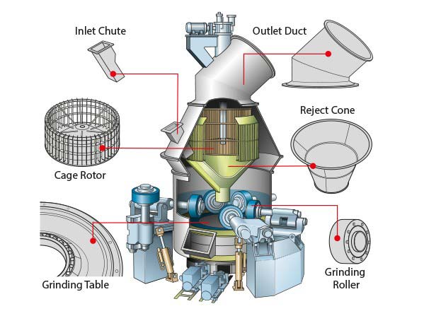
The structure of the vertical milling machine consists mainly of the housing, base, grind table, grind roller, roller arm and hydraulic cylinder arm, gearbox, hydraulic system, and powder selection unit.
Grind Table Assembly
The grind table is made of cast steel and is connected to the gearbox output flange through positioning pins and connecting bolts. The surface of the grind table is covered with a low manganese cast steel wear-resistant liner, which is fixed to the grind table using positioning devices. The liner of the grind table is divided into 20 pieces, with a concave grinding track on the surface. Surrounding the grind table is a material blocking ring, and the thickness of the bed between the grind table liner and the grind roller can be adjusted by adjusting the height of the blocking ring. The scraper is connected to the grind table with bolts and is used to handle the material.
Grind Roller Assembly
Grind Roller
The grind roller is composed of a surface-welded cast steel roller shell, which has high wear resistance and is fixed to the roller body using a taper ring and bolts. The roller body is assembled onto the roller shaft using tapered roller bearings and cylindrical roller bearings. The grind roller bearings are lubricated by a forced lubrication system. One side of the grind roller is equipped with a bearing end cover, and the other side is assembled to the bearing cover plate with bolts. The sliding parts between the bearing cover plate and the roller shaft are sealed with oil seals and shaft sleeves, and the sealing pressure from the sealing fan effectively prevents dust from entering the bearings. The surface-welded sealing protective cover provides effective protection against wear for the roller arm and rocker arm.
Grind Roller Lubrication Station
The oil in the oil tank of the grind roller lubrication station is extracted by the supply pump and then supplied to the bearings after passing through the oil cooler and dual filters. By adjusting the temperature control valve at the outlet of the oil cooler, the oil from the filtered part will be diverted to the bypass pipeline. The flow of oil entering the grind roller and entering the grind roller bearings can be adjusted by the bypass throttle valve between the oil inlet and outlet of the grind roller. The negative pressure of the return oil pump draws the oil back to the oil tank. The lubrication pipes are equipped with the following protective devices: flow meters for monitoring the lubrication flow of each bearing, and temperature measurement devices for the return oil, which are interlocked with the main motor of the vertical mill and the oil level of the tank. The heater in the oil tank is used to heat the oil in cold seasons.
Measurement of Grind Roller and Grind Table
Daily Maintenance Requirements for Grind Roller and Grind Table
Periodic measurements should be carried out to determine the wear of the grind roller and grind table liner.
If the wear of the grind roller and grind table liner increases and the gap becomes larger, adjustments should be made. Since both the grind roller and grind table liner are made of high-hardness materials, the following precautions should be taken: 1) Pay attention to avoiding collisions during transportation and storage. 2) Do not directly weld or cut on the roller shell and liner, as it may cause stress concentration. Check for any damage to the surface.
Measurement Standards
Grind Roller Measurement Guidelines:
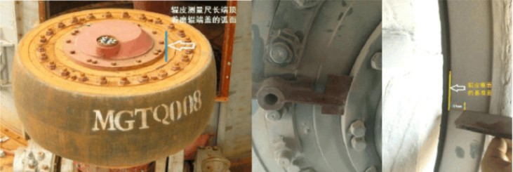
① The long end of the measurement gauge should rest against the curved surface of the roller end cover.
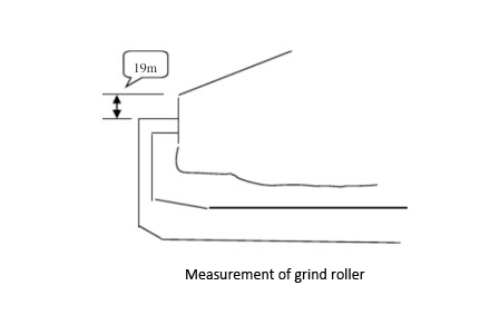
② The short end of the measurement gauge should be placed on the machined surface of the roller shell, with a reference plane of 19mm to the conical surface of the roller shell. (See the diagram below)
③ The entire measurement gauge should be perpendicular to the spherical surface of the roller shell and secured with the gauge's bolt or manually stabilized.
④ The person performing the measurement should have a sense of responsibility and a careful attitude to obtain accurate data.
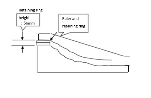
Grind Table Liner Measurement Guidelines:
① Place one end of the liner measurement gauge on the 56mm-high material blocking ring, aligning the gauge with the plane of the blocking ring. If there are any raised edges on the surface of the blocking ring, they should be polished flat.
② Ensure that the gauge is positioned correctly and not tilted.
③ The height of the 56mm material blocking ring is the standard measurement height for the first measurement. If the height of the blocking ring is adjusted during the production process, the measurement gauge height should be adjusted to 56mm when measuring the liner. Assuming the initial height of the blocking ring was a different dimension, subsequent measurements should be based on the initial dimension.
④ The person performing the measurement should have a sense of responsibility and a careful attitude to obtain accurate data.
Pre-measurement Instructions
The purpose of measurement is to ensure consistent measurement procedures each time, so that the data obtained is comparable.
If measurements were previously taken using a different method, continue measuring in the same manner and record the data to ensure comparability with the previous measurements. Additionally, please follow the measurement guidelines and establish new data for comparative analysis of similar vertical mill wear parts.
- stacker reclaimer
- industrial cyclone dust collector
- preheater
- casting parts
- rotary kiln
- ball mill
- vertical milling machine
- crusher machine
- grate cooler
- bucket elevator
- roller press
- others

This article covers rotary kiln drive types, key components, and fault analysis, focusing on troubleshooting and reliable operation....
AGICO Cement discusses the reduction gear box price in this article and provides cost-effective solution for the industrial reduction gearbox....
AGICO CEMENT revises problem that commonly happened on air lock valve and make progress to build the new type spare part....
- info@cementequipmentspares.com
- +86 18603725242
- Room 908, unit 1, building 2, Huaqiang Xintiandi, Xiange Avenue, Anyang, Henan Province, China